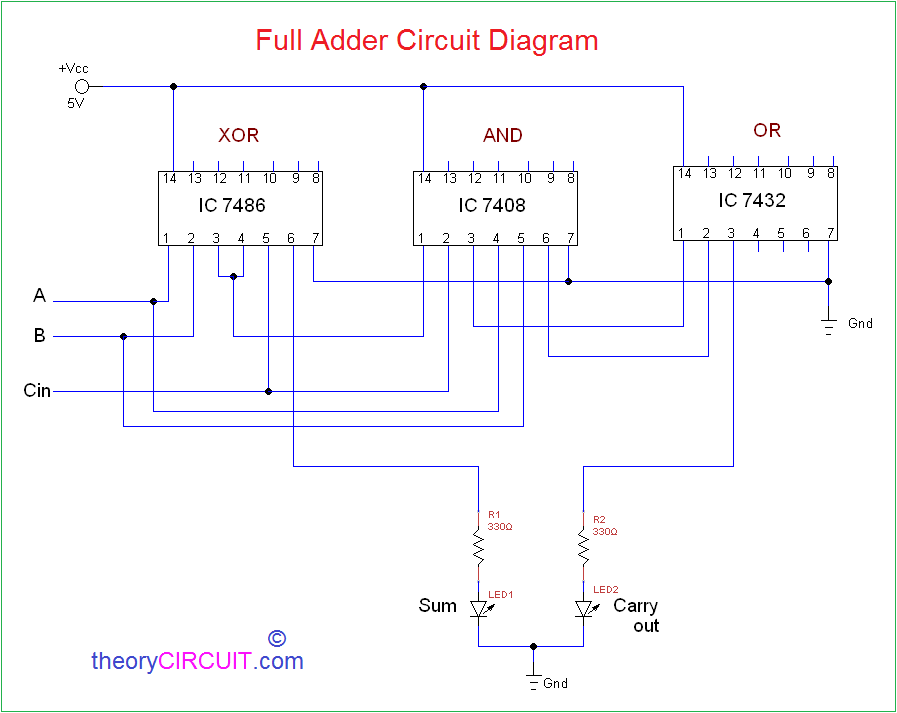
Full Adder Circuit Diagram Using Logic Gates
Adder gates gate logic switch circuit diagram dip input output multiple supply single 4-bit full adder using two-input nand gates ~ techno central Adder logic nand
A binary adder made using AND-OR array logic
Adder bit nand using gates input two gate circuit only Adder nor gate logic minimum implementing Full adder
Full adder
Half adder logic diagram and truth table / obe assignment: digitalA binary adder made using and-or array logic How can output from a single logic gate/dip switch supply input forAdder logic half implementation.
Adder logic projectiot123 introduction binary carry sum outputsAdder half circuit logic gate gates introduction purpose trouble determining having projects found building Logic gatesAdder logic binary circuit gates diagram using array make inputs labeled twice below also used.


